Something that is often not considered, but can be a source of failure, is the position of the spool and its path to the extruder. In order to facilitate the work of the extruder, the minimum resistance to traction of the filament should be sought. The higher the resistance, the harder the extruder motor has to work, generating more heat and increasing the possibility of pitch loss. In addition, the friction of the wheels with the filament will increase, causing more wear and dirt and increasing the possibility of bites in the filament.
Optimum coil position
The optimum coil location is the one that guarantees the shortest and straightest path to the extruder. In addition, the following points should be taken into account:
- PTFE tubes: If the distance between the spool and the extruder is high (usually more than 15-20 cm) or if it is not possible to place the spool directly on the extruder in direct systems, a PTFE tube should be used to guide the filament.
- If the PTFE tubing is used to lead the filament from the spool to the extruder, tubing with an internal cross-section that is slightly larger than the diameter of the filament should be used. Tubing with tight diameters will produce more friction and increase the stress on the motor.
- If the PTFE tubing is used to lead the filament from the extruder to the hotend (Bowden systems), the internal diameter must be adjusted to achieve the most homogeneous pressure possible. In these cases it is recommended to use high quality PTFE tubing with the lowest possible coefficient of friction.
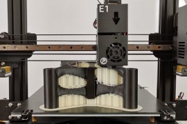
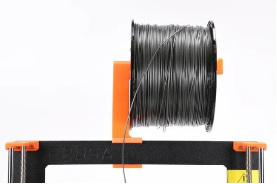
In either case, the travel should be as short as possible (maximum 80 cm in the case of Bowden systems) and with the largest possible radius of curvature. In addition, one end of the PTFE tube should be inserted directly into the extruder, while the other end should be placed tangent to the spool and at a distance of about 10 cm from the filament unwinding area.
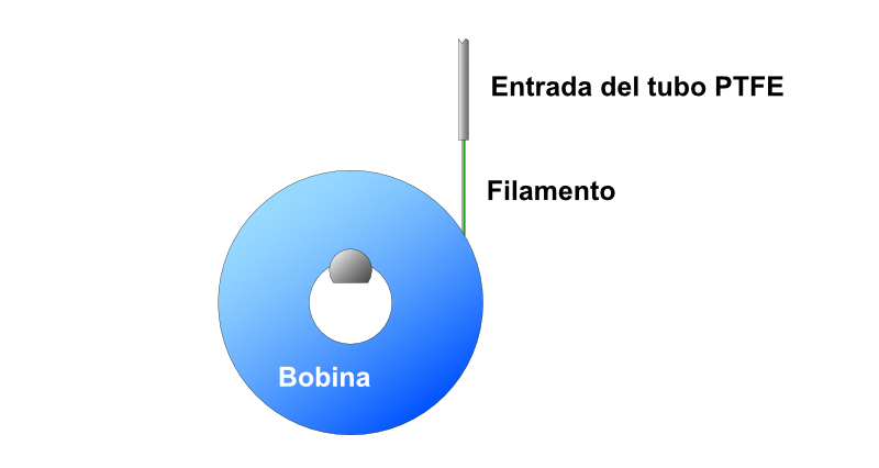
Image 1: Correct position of the PTFE tube inlet. Source Filament2print
- Spool holder: Although it may seem that it is best for the spool holder to exert as little friction as possible, this is not the case. It is true that the bobbin holder should not exert excessive friction, but neither should it allow the bobbin to turn freely. If the spool rotates too much, it will cause a loss of tension in the last few turns of filament, increasing the risk of overlapping as tension is regained.
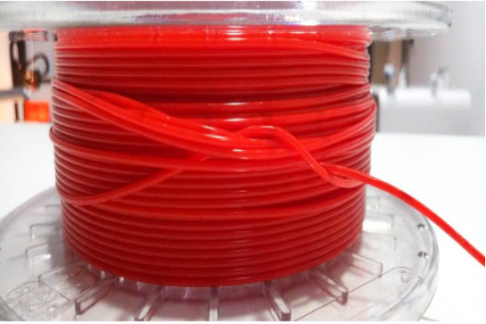
Image 2: Filament overlap in a coil. Source: Filament2print.com
Flexible Filaments
In the case of flexible filaments, it is particularly important to reduce the distance and friction. If there are considerable friction values, the filament will deform proportionally to the distance to the spool, reducing its cross-section due to the striction phenomenon. For practical purposes, this means that the real cross-section of the filament is not the nominal one, making it necessary to readjust the flux to avoid lack of extrusion. This is why it is sometimes necessary to use flow values above 115% in certain combinations of printer and flexible filament.
Filaments with metallic or ceramic fillers
One of the characteristics of the filaments with a high metallic or ceramic load intended for sintering is their high bending brittleness. This is why the way of feeding this type of filament is crucial to avoid breakage during printing.
Whenever you want to use this type of filament, it is advisable to do so in a 3D printer with a direct extrusion system and feed the filament in such a way that the path from the spool to the extruder is completely straight.
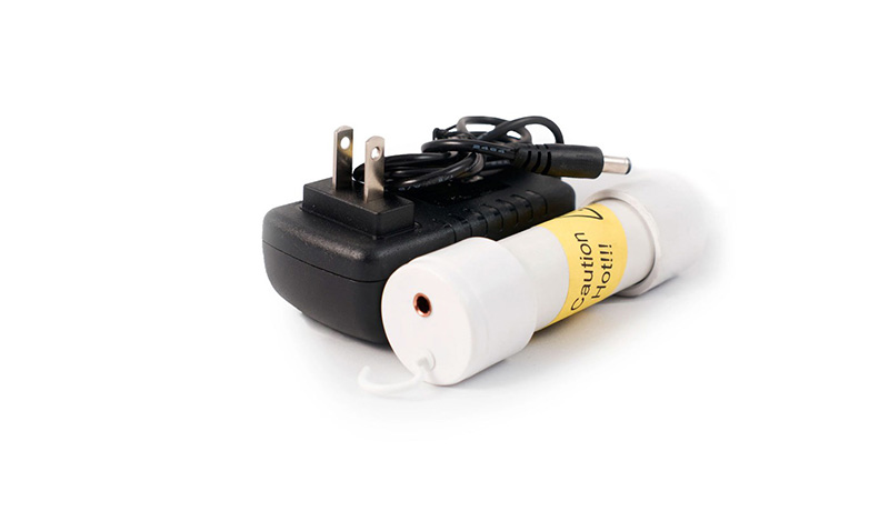
In the case of using Bowden printers, the largest possible bending radius in the path should be sought, even if this means using longer lengths of PTFE tubing. It may also be necessary to use devices that preheat the filament before it reaches the extruder in order to increase its ductility.